In my latest American Scientist column I’m packing spheres again. The goal this time is to maximize the number of contact points where spheres touch each other. For example, four spheres in a tetrahedral cluster have six contacts; this is the most possible, since each sphere touches all the rest. Over the past few years groups at Harvard and Yale have solved the maximum-contact problem for clusters of up to 11 spheres. Beyond that, nobody knows.
You can read all about it in your choice of PDF or living HTML, or you might even hunt down one of the rare and precious paper copies of the magazine.
The American Scientist column focuses on the work of the Harvard and Yale groups. Here I’m going to talk about my own adventures with contact-counting while creating illustrations for the article.
Geomag. When I visited some of the people behind the new contact-counting results, the first thing I noticed was their toys. They play with Geomag, a Swiss-made construction kit consisting of plastic-coated magnetic rods and half-inch polished steel balls. As soon as I got home, I bought a set for myself.
The pair of images below, showing two depictions of a regular tetrahedron, should make clear how clusters of spheres map onto Geomag models.
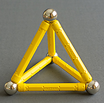
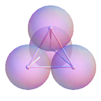
Assume all spheres have a radius of 1/2; then two tangent spheres have a center-to-center distance of 1. In the diagram at right I emphasize this fact by drawing a rod of unit length between the centers of all spheres that are in contact. The Geomag model at left reproduces this skeleton of rods, omitting the spheres themselves.
Natalie Arkus, who initiated the recent contact-counting work when she was a graduate student at Harvard (she is now at Rockefeller University) told me that the Geomag models were more than just a visual aid in her work. They were a tool for discovering new configurations and deciding which candidate structures are geometrically feasible.
Spinners. Having a 3D model to turn over in your hands is definitely the best way to understand the geometry of sphere clusters. Unfortunately, there is no <geomag> HTML tag that would allow me to embed a model in this web page.
A familiar alternative for 3D visualization is the stereoscopic pair:
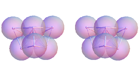
I’m not a big fan of this technique. Not everyone is adept at fusing the images without the help of a viewing device. And even when you can achieve the stereo illusion, it doesn’t help much in seeing what’s on the back side of the object.
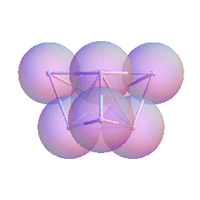 My own favorite trick for 3D visualization is to make the object twirl. It’s no secret that the human visual system does a better job of interpreting three-dimensional structures from a moving image than from a still one. This strategy is of no use in the print edition of the magazine, but I wanted to take advantage of it in the web edition and here on bit-player. If you haven’t done so already, hover your mouse pointer over the image above right; it should start spinning.
“Should,” I said. It works fine in Chrome and Safari and Opera. It even works in Internet Explorer. It works in Firefox version 3.6. But newer versions of Firefox give erratic results. Typically, the animation plays once but then dies. This bug was reported to Mozilla ages ago, but it persists in the latest Firefox update (16.0.1). Sorry for the rant, but it’s not like we’re dealing with bleeding-edge HTML5 technology here. The spinning sphere clusters are animated GIFs, a file format that goes back to 1989.
Coordinates. The first task in creating these illustrations is finding the coordinates of the sphere centers. Both the Harvard and the Yale groups have published extensive lists of coordinates, but I elected to roll my own. I wanted the animated figures to twirl around an axis of symmetry (in those cases where such an axis exists), and I found it easier to build up the geometry from scratch rather than making transformations from some other coordinate system.
Calculating coordinates is generally easy in these clusters because they all share an important property: Each sphere touches at least three other spheres. Suppose you want to add a fifth sphere to the tetrahedral cluster illustrated above. The only way the new sphere can touch three others is if it nestles into the central dimple in one of the four triangular faces of the tetrahedron. You can find the coordinates of the fifth center point by solving three simultaneous equations, defining distances to the three vertices of the triangular face. The equations have two solutions, defining points above and below the plane of the triangle. In the tetrahedron, one of those points is already occupied, and so the new sphere must be placed at the other solution point, on the opposite side of the plane of the triangle.
Having attached a fifth sphere to the cluster, you can use the same method to add a sixth, a seventh, and so on. In clusters made up entirely of regular tetrahedra, the process is especially straightforward. With other geometries it’s not always quite so obvious how to proceed, but with one exception I was able to construct all the clusters of interest by such step-by-step methods. (For the exception, see below under The Problematic Eight.)
Making Movies. With the coordinates in hand, assembling the diagrams is not complicated. At each sphere-center coordinate, draw a semitransparent sphere of radius 1/2. Then, to represent the Geomag-like skeleton of bonds, draw much smaller opaque spheres (radius 1/20) at each point, and add opaque tubes connecting the centers of spheres that are touching. How does the algorithm know which spheres are touching? Simply run through all \(n(n-1)/2\) pairs of spheres and select those whose euclidean distance is close enough to 1. (“Close enough” allows for some imprecision in the case of coordinates determined by numerical rather than analytic methods.)
To make the cluster twirl, I generate a series of views, rotating the object by some fixed, small angle between snapshots. If the object has rotational symmetry, there’s no need to twirl through a full 360 degrees. The tetrahedron, for example, makes do with a 120-degree subset.
All this was done in Mathematica, which has a rich set of three-dimensional graphics routines. Rotating a 3D object, for example, is a built-in function; all the trig and the linear algebra happens behind the scenes, without human intervention. Another Mathematica command exports the whole series of rotated views as a prepackaged GIF file. The entire makeSpinner procedure is a seven-line program. Nifty! 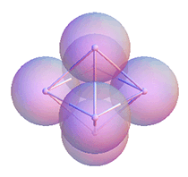 On the other hand, I had to struggle to defeat some of the Mathematica-knows-best automation. It seems a 3D graphic is always sized so that its 2D projection fills the allotted rectangular region on the screen. This may be a good idea most of the time, but it induces nausea with a rotating object. Try hovering on the octahedron at left. I found a directive (SphericalRegion → True) that I thought would cure this behavior, but it didn’t. If anyone reading this knows the right way to mark it up, please do let me know. I wound up with a kludge: I surrounded each cluster with a large, invisible sphere centered at the origin, fooling the Mathematica drawing routines into thinking that the cluster has constant width.
The Mathematica source code for building all the illustrations and animations is available here as a Mathematica notebook.
The Wiggler. Once I had all of those pirouetting purple bunches of grapes, I realized that the same animation apparatus could be adapted to show other kinds of motion.
Among all the sphere packings I’ve met in the course of this project, one of the most pivotal—and I choose that word carefully—is a nine-sphere configuration that exhibits a degree of torsional flexibility. Even though every sphere in the cluster touches at least three others, and therefore cannot move as an individual, the overall structure can twist without breaking any bonds.
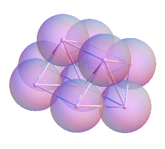
Animating this kind of motion is a little more complicated than displaying a rigid rotation of the entire cluster. At each time step, the two spheres at the top of the structure are twisted in opposite directions; then all the rest of the coordinates have to be recalulated to accommodate the change.
Note that the animation shows an exaggerated range of motion. The structure can twist only infinitessimally if you insist on maintaining all center-to-center distances at exactly 1. The animation was drawn with a tolerance of ±1 percent, which allows rotation of ±4 degrees before bonds start breaking.
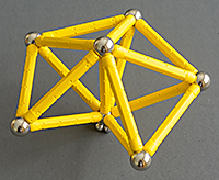 The Fivefold Way. If you spend any time playing with Geomag models, you are sure to stumble upon the structure shown at right, which consists of four tetrahedra joined along faces. It looks as if you might be able to add one more bond to close the gap, creating a solid of five joined tetrahedra. But it doesn’t work. The gap is slightly too wide. (By the way, I consider this a defect of our universe. We shouldn’t have to put up with such untidyness.)
 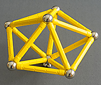 If you remove the central strut from the cluster of four tetrahedra, allowing the top and bottom spheres to move apart slightly, the gap closes and you arrive at a new cluster with exact fivefold symmetry, the pentagonal dipyramid, shown at left.
After the magazine had gone to press, I realized that the transition between these two structures could also be made clearer by an animation. Hover on the figure below to see it in action:
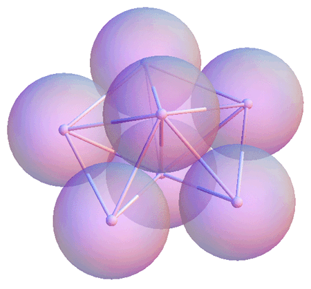
The Arkus Conjecture. The reversible transition between a tetratetrahedron and a pentagonal dipyramid requires breaking one bond and forming one new bond. Here’s another example of a single-bond exchange, where an octahedron is transformed into a cluster of three joined tetrahedra.
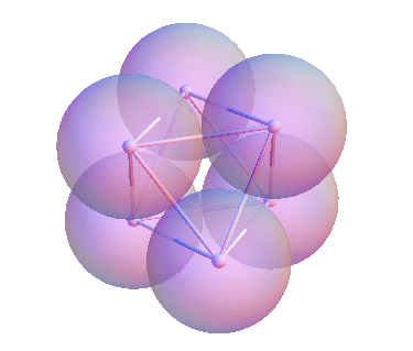
Arkus points out that all known maximum-contact packings are connected by some sequence of such single-bond moves. She conjectures that this fact will remain true for all larger clusters as well. If the conjecture is true, it will become much easier to catalogue the clusters for each value of n.
The Problematic Eight. At n=8 we encounter this peculiar structure, which can be understood as two pentagonal dipyramids smushed together at right angles:
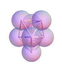
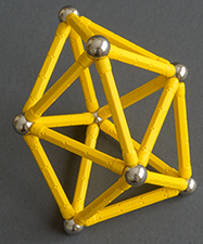
This object has stumped all my efforts to determine the coordinates by a step-by-step procedure, working from a known triangle to a fourth vertex, then a fifth, and so on. Making the Geomag model was easy, but to generate the Mathematica graphic I had to solve for five variables simultaneously.
Turn It Up to 12. The Harvard and Yale groups identified all configurations that maximize the contact number for clusters with up to 11 spheres. Beyond this limit is terra incognita. Nevertheless, there’s a 12-sphere solution that looks like a very plausible candidate.
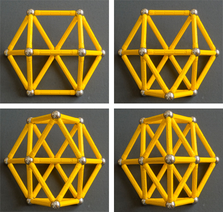
At the upper left is the nine-sphere “wiggler,” with 21 contacts. Then each of the subsequent frames, proceding from left to right and top to bottom, 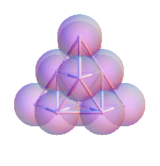 adds a single node and four more contacts. The final state, with 12 spheres and 33 contacts, is also shown at right in a spinning diagram. Is this structure the best that can be achieved with 12 spheres? For now the only reliable way to answer this question is to catalogue all other 12-sphere candidate clusters, and that would be a formidable undertaking.
I should add that this dense 12-sphere cluster is not a subset of the Kepler packing (hexagonal close-packed or face-centered cubic), and it cannot be extended to fill all of three-dimensional space.
Overflow. In American Scientist, my column this month spilled over two extra pages beyond my usual allotment. Nevertheless, there are still topics that I wasn’t been able to fit in. Some pointers:
- In the 1970s, M. R. Hoare and J. McInnes published a pioneering study of “small atomic clusters,” anticipating some of the recent results. They surveyed clusters with up to 13 atoms but considered only clusters that could be formed by combining tetrahedra and octahedra, ignoring various “new seeds” such as the pentagonal dipyramid. Reference: Hoare, M. R., and J. McInnes. 1976. Statistical mechanics and morphology of very small atomic clusters. Faraday Discussions of the Chemical Society 61:12–24.
- In 1995 Neil J. A. Sloane, R. H. Hardin, T. D. S. Duff and John Horton Conway suveyed “minimal-energy” clusters of up to 32 identical spheres. They defined the lowest-energy configuration as the one that minimizes the second moment of the spatial distribution, or in other words the sum of the squares of the distances from the center of mass. Although this criterion is quite different from the contact-counting method, many of the same clusters turn up. Reference: Sloane, N. J. A., R. H. Hardin, T. D. S. Duff and J. H. Conway. 1995. Minimal-energy clusters of hard spheres. Discrete and Computational Geometry 14:237–259.
- Conway and Sloane are also the authors of the standard reference work on the mathematics of sphere packing: Conway, J. H., and N. J. A. Sloane. 1999. Sphere Packings, Lattices, and Groups. 3rd edition. New York: Springer. I can also enthusiastically recommend a less-formal account of packing problems by Tomaso Aste and Denis Weaire: The Pursuit of Perfect Packing, 2008, second edition. New York: Taylor & Francis.
- If I ever get a chance to return to this topic, I would like to take a closer look at the work of Salvatore Torquato and his colleagues at Princeton, who study dense clusters in a context akin to the Newton kissing-number problem. For example, see: Hopkins, Adam B., Frank H. Stillinger and Salvatore Torquato. 2011. Densest local sphere-packing diversity. II. Application to three dimensions. Physical Review E 83:011304. (arXiv preprint)
Thanks. For helpful conversations and other kinds of guidance, my thanks to Rob Hoy of the University of South Florida, Corey O’Hern of Yale, Vinny Manoharan of Harvard and Natalie Arkus of Rockefeller University.

The almost-tiling with tetrahedra you call the “five-fold way” fascinated me in high school. Since there is a slight angle deficit, you might think that you can make it work with a little curvature in the 4th dimension, and indeed you can. Just as fitting 5 triangles at each corner leads to an icosahedron, fitting 5 tetrahedra around each edge — and 20 at each corner — leads to a 4-dimensional polytope called {3,3,5} with 600 tetrahedral cells.
Similarly, you can almost fit 4 dodecahedra at each corner. Doing so leads to the dual polytope, {5,3,3}, which has 120 dodecahedral cells.
Makes you wonder if the “five-fold way” gap can be closed in some non-Euclidean geometry.
The animations also don’t work for me in Google Reader (under Chrome). Reader must be scrubbing-out the JavaScript that tells it to switch between GIFs. I’m guessing it’s not a bug, but more a policy choice on the part of the Google Reader team. In any case, another data point for you…
Yes, I knew that and probably should have mentioned it. The Javascript gets bundled up into the RSS feed, but Reader strips it out. For the same reason, TeX comes through in source form rather than rendered by MathJax.
Of course you can always get the fully formatted version, with bells, whistles and fireworks, by clicking on the item title or the little northeast-pointing arrow next to it.
Your “problematic eight” is the deltahedron known as the snub disphenoid. It’s not surprising that you couldn’t find a step-by-step procedure to compute its coordinates: the analytical solution requires solving a cubic equation.