I’ve been goofing off in Nova Scotia for a few days. In Halifax I climbed up to the Citadel, a hilltop fortress built to protect the city from the French and later rebuilt to fend off the Americans; now it welcomes both those nationalities and anyone else willing to pay $12 for the tour and the costume show.
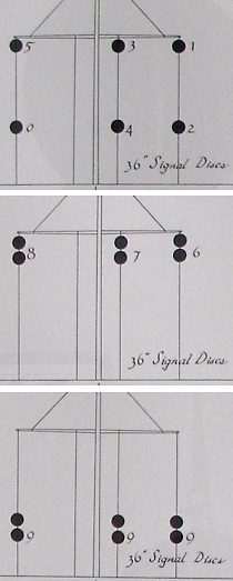 In one room of the museum I discovered the curious diagrams reproduced at right. These figures are extracted from a poster on military codes designed for ship-to-shore communication. Signals were sent by hoisting large balls or disks on a mast reaching high above the fortress ramparts; ships in the harbor could reply by raising similar signal disks on their own masks.
The part of the code shown here obviously pertains to the transmission of numbers, but I’ve never seen a weirder system of numeration. Based on these diagrams and others, I infer that the signal disks were raised on three halyards. (A fourth halyard is present in the diagrams but always seems to be empty.) Each halyard could display zero or one or two disks, and each displayed disk could be in either an upper or a lower position. That comes to five possible patterns per halyard, and thus 53 = 125 patterns in all. What baffles me is why the ten decimal digits were assigned to the specific patterns shown in the diagrams. Who counts in the sequence 1, 2, 3, 4, 5, 0, 6, 7, 8, 9, 9, 9?
I’m not even sure I understand the basic signaling protocol. When I first looked at the poster, I assumed that the ten digits were represented thus:
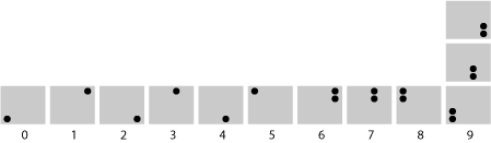
Presumably, the three encodings for ’9′ were equivalent, and any of them could be used at the signaler’s option.
Later, after much musing over this puzzle, I decided that another interpretation of the diagrams seemed more plausible:
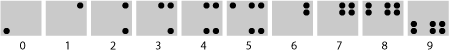
In this scheme at least the numerals from 1 through 5 have some kind of logic to them, in that the number of disks shown matches the numeral being transmitted; in essence we have a unary notation within that limited range. On the other hand, if this interpretation of the diagrams is correct, we have to ask: Why did the designers stop at 5? They could have extended the same unary scheme to the range from 1 to 6, and then used doubled disks at the top of the mast for the numerals 7, 8 and 9.
If we were creating a code like this today, I’m sure everyone’s first impulse would be a system based on binary notation. It’s not terribly surprising that the British naval authorities circa 1850 didn’t think of that. But I still find the apparent arbitrariness of this numerical code utterly perplexing. Am I missing some pattern in the data, either obvious or subtle? (I suppose the encoding could be deliberately obscure, but there’s no evidence that this was meant to be a secret code, and the mere existence of the poster—which appears to be a 19th-century artifact—suggests otherwise.)
Added 2009-09-10: Below is the signal mask on which the disks were displayed, seen from the landward side. The disks (actually fabric-covered crossed hoops, which have an approximately circular cross section from any azimuth) were 36 inches in diameter. I think the diameter of the mast is about 12 inches at the base.

* * *
The Googleverse has so far failed to solve this mystery for me, but in the process of searching I stumbled upon a remarkable book that suggests there was some lucid thinking in the 19th century on themes that we would now identify as information theory. The book is A Manual of Signals: For the Use of Signal Officers in the Field, and for Military and Naval Students, Military Schools, Etc., by Albert J. Myer. The full text is available on Google Books in either HTML or PDF.
Myer founded the U.S. Army Signal Corps just before the outbreak of the Civil War. He had studied medicine, writing a dissertation on “A New Sign Language for Deaf Mutes,” and had also worked as a telegraph operator. Then, in the army, he devised the signaling method commonly known as wigwag, using a single flag waved to the left and the right. Fort Myer in Virginia is named for him. (These biographical snippets come from a Signal Corps history, which offers much further detail.)
Myer’s book was first published in 1864 and then revised in 1868, but it takes quite a modern mathematical approach to problems of communication and information. He begins with a tutorial on permutations and combinations, then applies these ideas to the encoding of signals:
We wish for example to make a large number of signals…. We take any few different and simple known signs, sounds, motions, or indications, which we can easily make, and we join them together, twos or threes, or more at a time, making one after another into many and different and more complex signs or arrangements. Each of these new signs becomes, when a meaning is given to it, a signal. We can increase the number of such signals to any limit by continuing to join together the known signals in greater numbers or in new arrangements.
That’s a pretty good description of Σ*, the set of all strings over a finite alphabet.
* * *
Guest update 2009-09-10: The following comes from Barry Cipra.
I have an idea for an alternative interpretation of the way digits are meant to be represented by disks on halyards. My basic premise is that a distant viewer can tell the difference between a disk being up high and it being down low, but cannot accurately judge which halyard a disk is on unless there’s at least one disk on each halyard. (In particular, two disks on outer halyards could be confused with two disks on adjacent halyards if the mast is at an angle to the distant viewer.) In this case, the digits 0 through 9 can be unambiguously represented as follows:

In other words, basically your second interpretation for 0 through 8, but with an extra “anchoring” pip for the numbers 1 through 5, but your first interpretation for the number 9. This makes it clear why the small-number format stops at 5.
If my premise is correct (or accepted as correct), then out of the 216 distinct patterns, there are only 1+5+25+125 = 156 unambiguous signals possible. That is, there is 1 signal with no halyards having any disks, 5 with exactly one halyard showing at least one disk, 25 with exactly two halyards showing at least one disk each, and 125 with disks showing on all three halyards.
But maybe we should also require the meaning of a pattern to be unambiguous when the orientation of the ship is uncertain — i.e., A,B,C should have the same meaning as C,B,A. If I’ve thought through things correctly, this cuts the number of unambiguous signals down to 1+5+15+75 = 96.
It would be great to find out how the Navy really did things!
* * *
Update 2009-09-17: Many thanks to Jim Ward (in the comments) for unearthing a 2007 document by Spurgeon G. Roscoe that illuminates the history of this signaling system, even if it doesn’t quite pin down how the code worked.
Roscoe describes a system of signaling towers founded by Edward, Duke of Kent, during his busy tenure as military commander in the Maritime Provinces at the end of the 18th century. Kent’s optical telegraph line was to run from Halifax to Annapolis in Nova Scotia and on to Fredericton in New Brunswick. It is not known with certainty how much of the network was completed or whether it ever served as a practical communications link. (Roscoe is skeptical, pointing out among other things that the territory around the Bay of Fundy is very foggy.)
The chart on exhibit at the Citadel in Halifax is not directly connected with the Kent telegraph system; it comes from a later era and is identified as a device for ship-to-shore communication; nevertheless, there is an unmistakable familial resemblance. Sketches reproduced by Roscoe give the following code system for the Duke of Kent’s overland telegraph:

This is merely a cyclic permutation of positions 0, 6, 7, 8 and 9 in the Citadel code. (On first glance there also seems to be a mirror reversal involved, but that’s not the case; we’re merely looking at the signal mast from the opposite direction.)
Roscoe says nothing about how to interpret these diagrams—whether, for example, the display for “6″ consisted of six disks or a single disk in the lower right corner, or one of the other schemes discussed above or in the comments. But his description of how messages were composed seems so impossibly cumbersome that it leaves me wondering if this plan was ever really put into practice. Apparently, alphabetic characters did not have codes of their own; each letter was encoded in a sequence of numerals. In one system, “A” was 2, 3, 0; “B” was 1, 4, 0; “Q” was 4; “T” was 2, 3. (The compact, single-digit encoding of “Q” makes this a kind of anti-Hamming code.) Can anything so maladaptive have survived the trial of use in the field?
Update 2009-09-22: This is a response to Carl Witty’s comment. I’m putting it here in the main text rather than in a further comment because I think Witty has essentially solved the mystery.
Witty’s interpretation of the Roscoe manuscript rules out all schemes in which the code is “cumulative” — where the signal for 3, for example, consists of the disks numbered 1, 2 and 3. Instead, digits 1 through 6 are each represented by a single displayed disk, and digits 7 through 9 each consist of a single pair of disks. (The triple code for 9 is to be interpreted as an “OR”: Any of the three positions can be used with the same meaning.) Then these digits — which are really just opaque symbols, with no numerical meaning — are combined in various ways to represent the letters of the alphabet and the numbers from 1 to 99. (Supplementary flags bring the range of numbers up to 499.)
Thus when Roscoe indicates that the letter S has the coding “1, 3, 5,” that means the disks labeled 1, 3 and 5 are all displayed simultaneously in order to transmit an S.
There’s a test for this hypothesis. If the scheme is to be workable, the alphabetic and numerical codes composed by displaying two or three or four digits at once must have a particular form. There can be no repeated digits in any encoding, and no two of the digits can use the same position on the mast. Specifically, in the Duke of Kent code illustrated in the 2009-09-17 update above, there can be no composite code that calls for both a 1 and a 7, or a 3 and an 8 or a 9 and a 5.
Does the code transcribed by Roscoe pass this test? Roscoe actually gives two codes, both apparently found in an 1802 “Signal Book” from Camperdowne Station in Nova Scotia. Roscoe’s second listing of alphabetic and numeric encodings does indeed satisfy the constraints. Indeed, it obeys a stronger restriction: No combination of symbols in the code calls for hoisting more than two disks on a single halyard. For example, the code avoids not only 1 and 7 but also 2 and 7.
The other code that Roscoe lists fails the test — or so it seems at first glance. There are patterns such as “1, 7″ encoding the number 54 and “3, 8″ for 64. But on looking closer, it appears that this code adheres to a different set of constraints: There are no instances where a 6 appears together with either a 1 or 2, or where 7 is combined with 3 or 4, or finally where 8 comes together with 5 or 0. These are exactly the restrictions that have to be applied in the Citadel code!