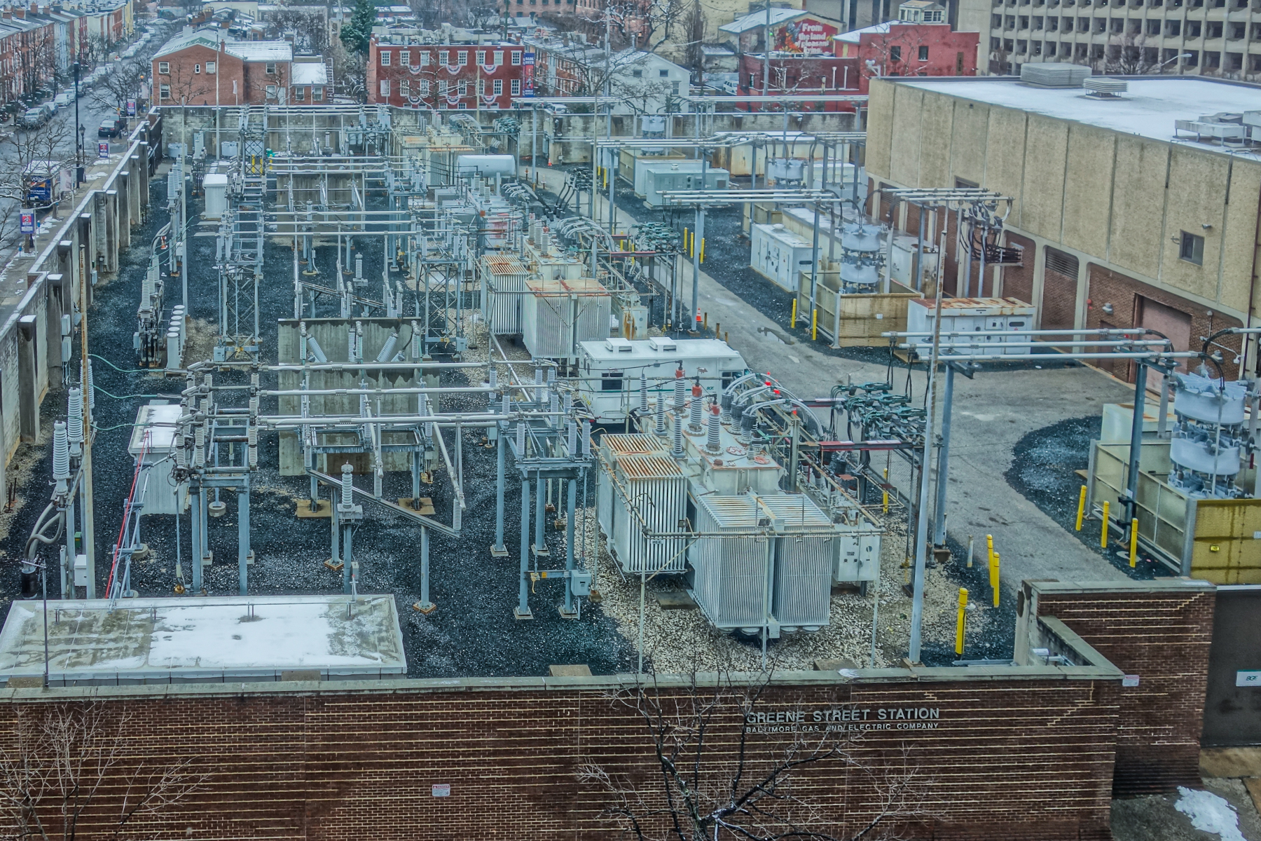
On my visit to Baltimore for the Joint Mathematics Meetings a couple of weeks ago, I managed to score a hotel room with a spectacular scenic view. My seventh-floor perch overlooked the Greene Street substation of the Baltimore Gas and Electric Company, just around the corner from the Camden Yards baseball stadium.
Some years ago, writing about such technological landscapes, I argued that you can understand what you’re looking at if you’re willing to invest a little effort:
At first glance, a substation is a bewildering array of hulking steel machines whose function is far from obvious. Ponderous tanklike or boxlike objects are lined up in rows. Some of them have cooling fins or fans; many have fluted porcelain insulators poking out in all directions…. If you look closer, you will find there is a logic to this mélange of equipment. You can make sense of it. The substation has inputs and outputs, and with a little study you can trace the pathways between them.
If I were writing that passage now, I would hedge or soften my claim that an electrical substation will yield its secrets to casual observation. Each morning in Baltimore I spent a few minutes peering into the Greene Street enclosure. I was able to identify all the major pieces of equipment in the open-air part of the station, and I know their basic functions. But making sense of the circuitry, finding the logic in the arrangement of devices, tracing the pathways from inputs to outputs—I have to confess, with a generous measure of chagrin, that I failed to solve the puzzle. I think I have the answers now, but finding them took more than eyeballing the hardware.
Basics first. A substation is not a generating plant. BGE does not “make” electricity here. The substation receives electric power in bulk from distant plants and repackages it for retail delivery.  At Greene Street the incoming supply is at 115,000 volts (or 115 kV). The output voltage is about a tenth of that: 13.8 kV. How do I know the voltages? Not through some ingenious calculation based on the size of the insulators or the spacing between conductors. In an enlargement of one of my photos I found an identifying plate with the blurry and partially obscured but still legible notation “115/13.8 KV.”
The biggest hunks of machinery in the yard are the transformers (photo below), which do the voltage conversion. Each transformer is housed in a steel tank filled with oil, which serves as both insulator and coolant. Immersed in the oil bath are coils of wire wrapped around a massive iron core. Stacks of radiator panels, with fans mounted underneath, help cool the oil when the system is under heavy load. A bed of crushed stone under the transformer is meant to soak up any oil leaks and reduce fire hazards.
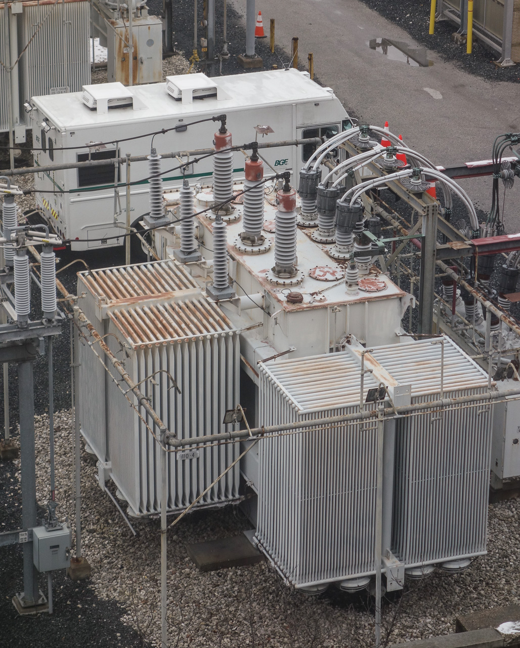
Electricity enters and leaves the transformer through the ribbed gray posts, called bushings, mounted atop the casing. A bushing is an insulator with a conducting path through the middle. It works like the rubber grommet that protects the power cord of an appliance where it passes through the steel chassis. The high-voltage inputs attach to the three tallest bushings, with red caps; the low-voltage bushings, with dark gray caps, are shorter and more closely spaced. Notice that each high-voltage input travels over a single slender wire, whereas each low-voltage output has three stout conductors. That’s because reducing the voltage to one-tenth increases the current tenfold.
What about the three slender gray posts just to the left of the high-voltage bushings? They are lightning arresters, shunting sudden voltage surges into the earth to protect the transformer from damage.
Perhaps the most distinctive feature of this particular substation is what’s not to be seen. There are no tall towers carrying high-voltage transmission lines to the station. 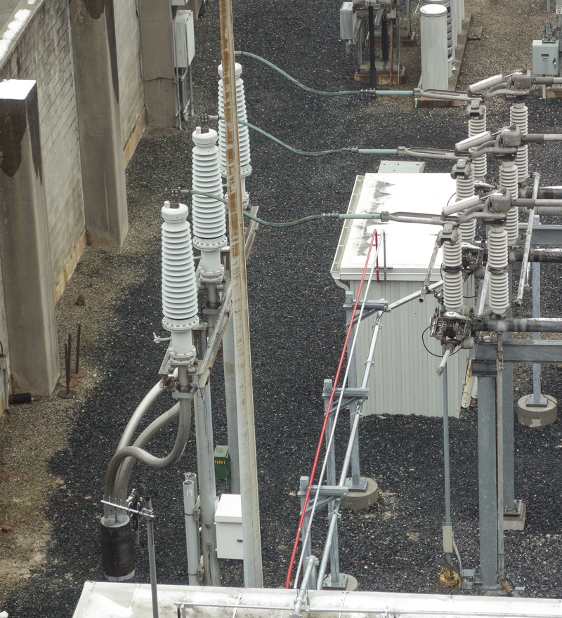 Clearing a right of way for overhead lines would be difficult and destructive in an urban center, so the high-voltage “feeders” run underground. In the photo at right, near the bottom left corner, a bundle of three metal-sheathed cables emerges from the earth. Each cable, about as thick as a human forearm, has a copper or aluminum conductor running down the middle, surrounded by insulation. I suspect these cables are insulated with layers of paper impregnated with oil under pressure; some of the other feeders entering the station may be of a newer design, with solid plastic insulation. Each cable plugs into the bottom of a ceramic bushing, which carries the current to a copper wire at the top. (You can tell the wire is copper because of the green patina.)
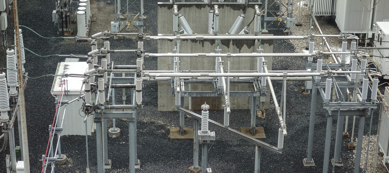
Connecting the feeder input to the transformer is a set of three hollow aluminum conductors called bus bars, held high overhead on steel stanchions and ceramic insulators. At both ends of the bus bars are mechanical switches that open like hinged doors to break the circuit. I don’t know whether these switches can be opened when the system is under power or whether they are just used to isolate components for maintenance after a feeder has been shut down. Beyond the bus bars, and hidden behind a concrete barrier, we can glimpse the bushings atop a different kind of switch, which I’ll return to below.
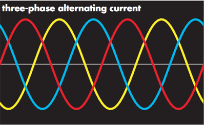 At this point you might be asking, why does everything come in sets of three—the bus bars, the feeder cables, the terminals on the transformer? It’s because electric power is distributed as three-phase alternating current. Each conductor carries a voltage oscillating at 60 Hertz, with the three waves offset by one-third of a cycle. If you recorded the voltage between each of the three pairs of conductors (AB, AC, BC), you’d see a waveform like the one above at left.
At the other end of the conducting pathway, connected to three more bus bars on the low-voltage side of the transformer, is an odd-looking stack of three large drums. These
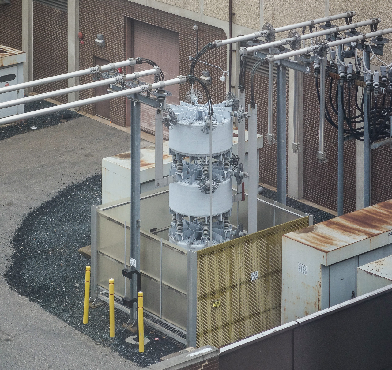
are current-limiting reactors (no connection with nuclear reactors). They are coils of thick conductors wound on a stout concrete armature. Under normal operating conditions they have little effect on the transmission of power, but in the milliseconds following a short circuit, the sudden rush of current generates a strong magnetic field in the coils, absorbing the energy of the fault current and preventing damage to other equipment.
So those are the main elements of the substation I was able to spot from my hotel window. They all made sense individually, and yet I realized over the course of a few days that I didn’t really understand how it all works together. My doubts are easiest to explain with the help of a bird’s eye view of the substation layout, cribbed from Google Maps:
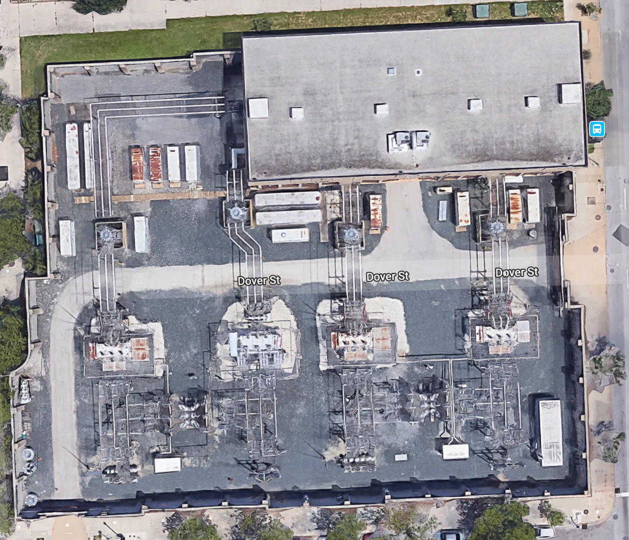
My window vista was from off to the right, beyond the eastern edge of the compound. In the Google Maps view, the underground 115 kV feeders enter at the bottom or southern edge, and power flows northward through the transformers and the reactor coils, finally entering the building that occupies the northeast corner of the lot. Neither Google nor I can see inside this windowless building, but I know what’s in there, in a general way. That’s where the low-voltage (13.8 kV) distribution lines go underground and fan out to their various destinations in the neighborhood.
Let’s look more closely at the outdoor equipment. There are four high-voltage feeders, four transformers, and four sets of reactor coils. Apart from minor differences in geometry (and one newer-looking, less rusty transformer), these four parallel pathways all look alike. It’s a symmetric four-lane highway. Thus my first hypothesis was that four independent 115 kV feeders supply power to the station, presumably bringing it from larger substations and higher-voltage transmission lines outside the city.
However, something about the layout continued to bother me. If we label the four lanes of the highway from left to right, then on the high-voltage side, toward the bottom of the map view, it 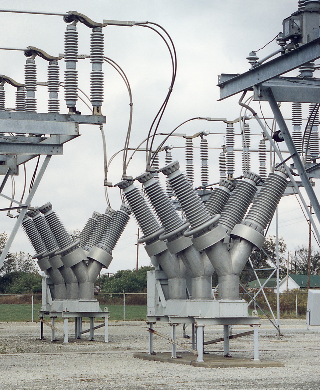 looks like there’s something connecting lanes 1 and 2 and, and there’s a similar link between lanes 3 and 4. From my hotel window the view of this device is blocked by a concrete barricade, and unfortunately the Google Maps image does not show it clearly either. (If you zoom in for a closer view, the goofy Google compression algorithm will turn the scene into a dreamscape where all the components have been draped in Saran Wrap.) Nevertheless, I’m quite sure of what I’m looking at. The device connecting the pairs of feeders is a high-voltage three-phase switch, or circuit breaker, something like the ones seen in the image at right (photographed at another substation, in Missouri.) The function of this device is essentially the same as that of a circuit breaker in your home electrical panel. You can turn it off manually to shut down a circuit, but it may also “trip” automatically in response to an overload or a short circuit. The concrete barriers flanking the two high-voltage breakers at Greene Street hint at one of the problems with such switches. Interrupting a current of hundreds of amperes at more than 100,000 volts is like stopping a runaway truck: It requires absorbing a lot of energy. The switch does not always survive the experience.
When I first looked into the Greene Street substation, I was puzzled by the absence of breakers at the input end of each main circuit. I expected to see them there to protect the transformers and other components from overloads or lightning strikes. I think there are breakers on the low-voltage side, tucked in just behind the transformers and thus not clearly visible from my window. But there’s nothing on the high side. I could only guess that such protection is provided by breakers near the output of the next substation upstream, the one that sends the 115 kV feeders into Greene Street.
That leaves the question of why pairs of circuits within the substation are cross-linked by breakers. I drew a simplified diagram of how things are wired up:
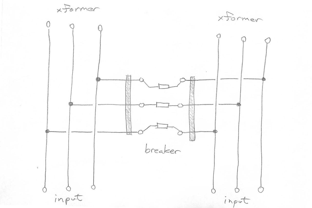
Two adjacent 115 kV circuits run from bottom to top; the breaker between them connects corresponding conductors—left to left, middle to middle, right to right. But what’s the point of doing so?
I had some ideas. If one transformer were out of commission, the pathway through the breaker could allow power to be rerouted through the remaining transformer (assuming it could handle the extra load). Indeed, maybe the entire design simply reflects a high level of redundancy. There are four incoming feeders and four transformers, but perhaps only two are expected to operate at any given time. The breaker provides a means of switching between them, so that you could lose a circuit (or maybe two) and still keep all the lights on. After all, this is a substation supplying power to many large facilities—the convention center (where the math meetings were held), a major hospital, large hotels, the ball park, theaters, museums, high-rise office buildings. Reliability is important here.
After further thought, however, this scheme seemed highly implausible. There are other substation layouts that would allow any of the four feeders to power any of the four transformers, allowing much greater flexibility in handling failures and making more efficient use of all the equipment. Linking the incoming feeders in pairs made no sense.
I would love to be able to say that I solved this puzzle on my own, just by dint of analysis and deduction, but it’s not true. When I got home and began looking at the photographs, I was still baffled. The answer eventually came via Google, though it wasn’t easy to find. Before revealing where I went wrong, I’ll give a couple of hints, which might be enough for you to guess the answer.
Hint 1. I was led astray by a biased sample. I am much more familiar with substations out in the suburbs or the countryside, partly because they’re easier to see into. Most of them are surrounded by a chain-link fence rather than a brick wall. But country infrastructure differs from the urban stuff.
Hint 2. I was also fooled by geometry when I should have been thinking about topology. To understand what you’re seeing in the Greene Street compound, you have to get beyond individual components and think about how it’s all connected to the rest of the network.
The web offers marvelous resources for the student of infrastructure, but finding them can be a challenge. You might suppose that the BGE website would have a list of the company’s facilities, and maybe a basic tutorial on where Baltimore’s electricity comes from. There’s nothing of the sort (although the utility’s parent company does offer thumbnail descriptions of some of their generating plants). Baltimore City websites were a little more helpful—not that they explained any details of substation operation, but they did report various legal and regulatory filings concerned with proposals for new or updated facilities. From those reports I learned the names of several BGE installations, which I could take back to Google to use as search terms.
One avenue I pursued was figuring out where the high-voltage feeders entering Greene Street come from. I discovered a substation called Pumphrey about five miles south of the city, near BWI airport, which seemed to be a major nexus of transmission lines. 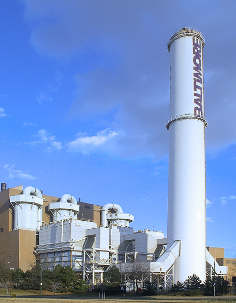 In particular, four 115 kV feeders travel north from Pumphrey to a substation in the Westport neighborhood, which is about a mile south of downtown. The Pumphrey-Westport feeders are overhead lines, and I had seen them already. Their right of way parallels the light rail route I had taken into town from the airport. Beyond the Westport substation, which is next to a light rail stop of the same name, the towers disappear. An obvious hypothesis is that the four feeders dive underground at Westport and come up at Greene Street. This guess was partly correct: Power does reach Greene Street from Westport, but not exclusively.
At Westport BGE has recently built a small, gas-fired generating plant, to help meet peak demands. The substation is also near the Baltimore RESCO waste-to-energy power plant (photo above), which has become a local landmark. (It’s the only garbage burner I know that turns up on postcards sold in tourist shops.) Power from both of these sources could also make its way to the Greene Street substation, via Westport.
I finally began to make sense of the city’s wiring diagram when I stumbled upon some documents published by the PJM Interconnection, the administrator and coordinator of the power “pool” in the mid-Atlantic region. PJM stands for Pennsylvania–New Jersey–Maryland, but it covers a broader territory, including Delaware, Ohio, West Virginia, most of Virginia, and parts of Kentucky, Indiana, Michigan, and Illinois. Connecting to such a pool has important advantages for a utility. If an equipment failure means you can’t meet your customers’ demands for electricity, you can import power from elsewhere in the pool to make up the shortage; conversely, if you have excess generation, you can sell the power to another utility. The PJM supervises the market for such exchanges.
The idea behind power pooling is that neighbors can prop each other up in times of trouble; however, they can also knock each other down. As a condition of membership in the pool, utilities have to maintain various standards for engineering and reliability. PJM committees review plans for changes or additions to a utility’s network. It was a set of Powerpoint slides prepared for one such committee that first alerted me to my fundamental misconception. One of the slides included the map below, tracing the routes of 115 kV feeders (green lines) in and around downtown Baltimore.
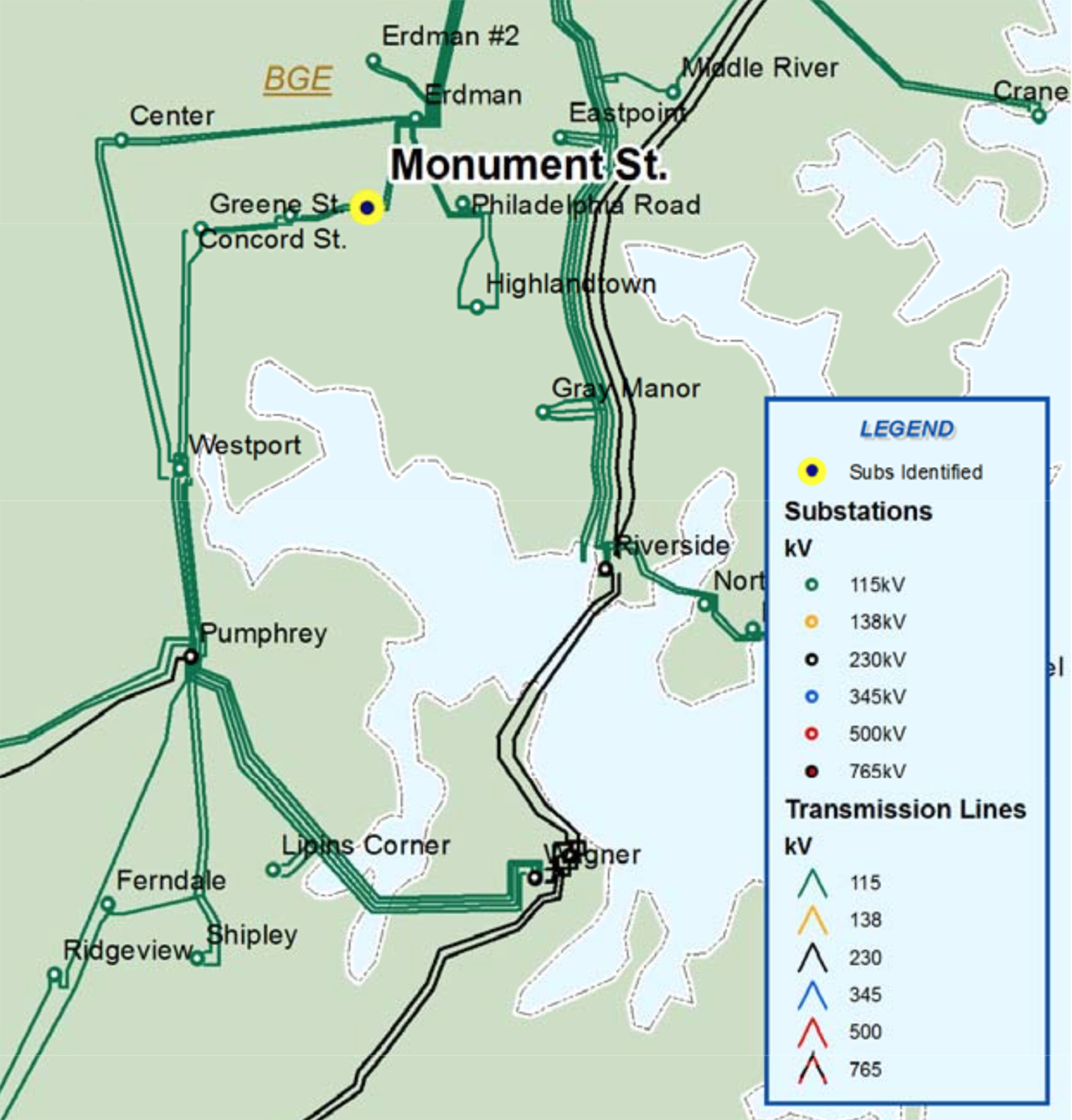
I had been assuming—even though I should have known better—that the distribution network is essentially treelike, with lines radiating from each node to other nodes but never coming back together. For low-voltage distribution lines in sparsely settled areas, this assumption is generally correct. If you live in the suburbs or in a small town, there is one power line that runs from the local substation to your neighborhood; if a tree falls on it, you’re in the dark until the problem is fixed. There is no alternative route of supply. But that is not the topology of higher-voltage circuits. The Baltimore network consists of rings, where power can reach most nodes by following either of two pathways.
In the map we can see the four 115 kV feeders linking Pumphrey to Westport. From Westport, two lines run due north to Greene Street, then make a right turn to another station named Concord Street.
This double-ring architecture calls for a total reinterpretation of how the Greene Street substation works. I had imagined the four 115 kV inputs as four lanes of one-way traffic, all pouring into the substation and dead-ending in the four transformers. In reality we have just two roadways, both of which enter the substation and then leave again, continuing on to further destinations. And they are not one-way; they can both carry traffic in either direction. The transformers are like exit ramps that siphon off a portion of the traffic while the main stream passes by.
At Greene Street, two of the underground lines entering the compound come from Westport, but the other two proceed to Concord Street, the next station around the ring. What about the breakers that sit between the incoming and outgoing branches of each circuit? They open up the ring to isolate any section that experiences a serious failure. For example, a short circuit in one of the cables running between Greene Street and Concord Street would cause breakers at both of those stations to open up, but both stations would continue to receive power coming around the other branch of the loop.
This revised interpretation was confirmed by another document made available by PJM, this one written by BGE engineers as an account of their engineering practices for transmission lines and substations. It includes a schematic diagram of a typical downtown Baltimore substation. The diagram makes no attempt to reproduce the geometric layout of the components; it rearranges them to make the topology clearer.
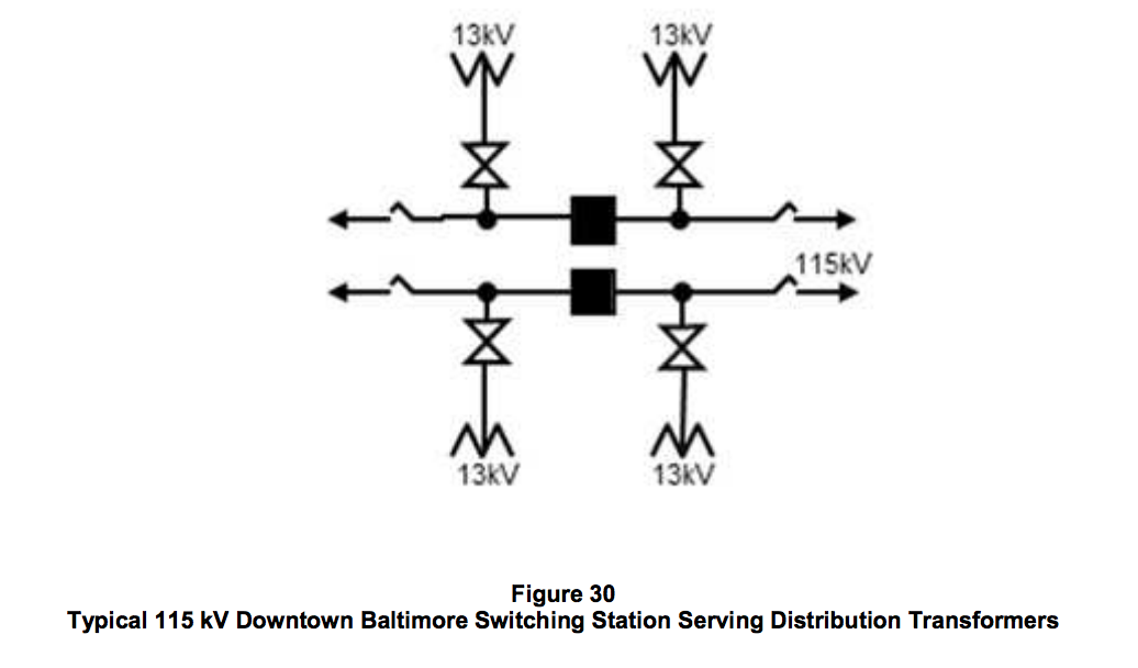
The two 115 kV feeders that run through the substation are shown as horizontal lines; the solid black squares in the middle are the breakers that join the pairs of feeders and thereby close the two rings that run through all the downtown substations. The transformers are the W-shaped symbols at the ends of the branch lines.
A mystery remains. The symbol ![]() represents a disconnect switch, a rather simple mechanical device that generally cannot be operated when the power line is under load. The
represents a disconnect switch, a rather simple mechanical device that generally cannot be operated when the power line is under load. The ![]() symbol is identified in the BGE document as a circuit switcher, a more elaborate device capable of interrupting a heavy current. In the Greene Street photos, however, the switches at the two ends of the high-voltage bus bars appear almost identical. I’m not seeing any circuit switchers there. But, as should be obvious by now, I’m capable of misinterpreting what I see.
symbol is identified in the BGE document as a circuit switcher, a more elaborate device capable of interrupting a heavy current. In the Greene Street photos, however, the switches at the two ends of the high-voltage bus bars appear almost identical. I’m not seeing any circuit switchers there. But, as should be obvious by now, I’m capable of misinterpreting what I see.

Thanks for this post. As always, informative and intriguing. So how is JMM this year?